
Products
Our company is always dedicated to providing powerful products that meet customers’ requirements and customization is available for small quantity.
Products


Feature
Max.load:12000N
Product class lP66
Compact mechanical system
Built-in limit switches
Imported POT/HALL sensors (options)
CE certificated
Widely work in the harsh environment
PDF Download
Basic Spec.
.jpg")
Technical Info
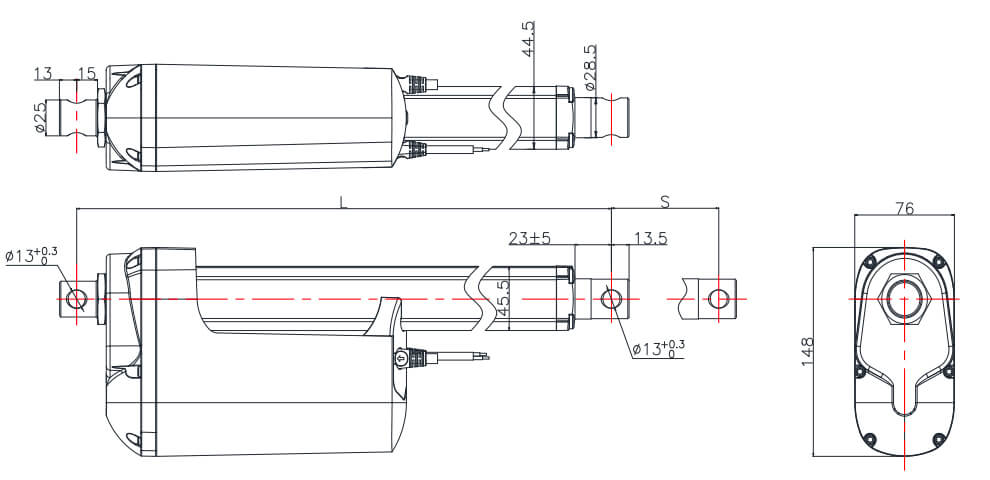
Mounting length
Dimension
S: Stroke, the travel length of actuator
L: Length, the fully retracted length of actuator from front hole centre to rear hole centre
Hall Sensor Signal

Notice: Hall sensor power supply 3.3V-24V, recommend to use 5V or 12V
POT
Signal Output
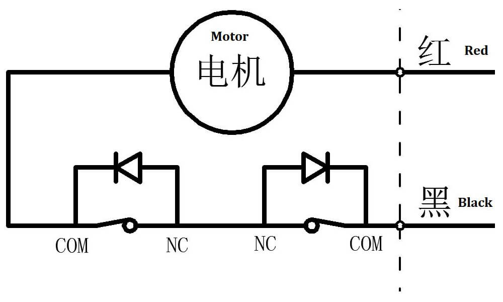
Standard limit switch diagram
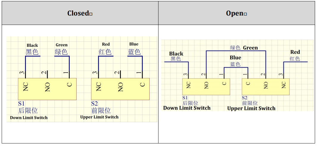
Limit switch signal output
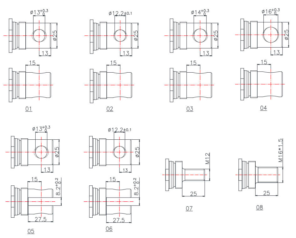
Attachment Options
Front
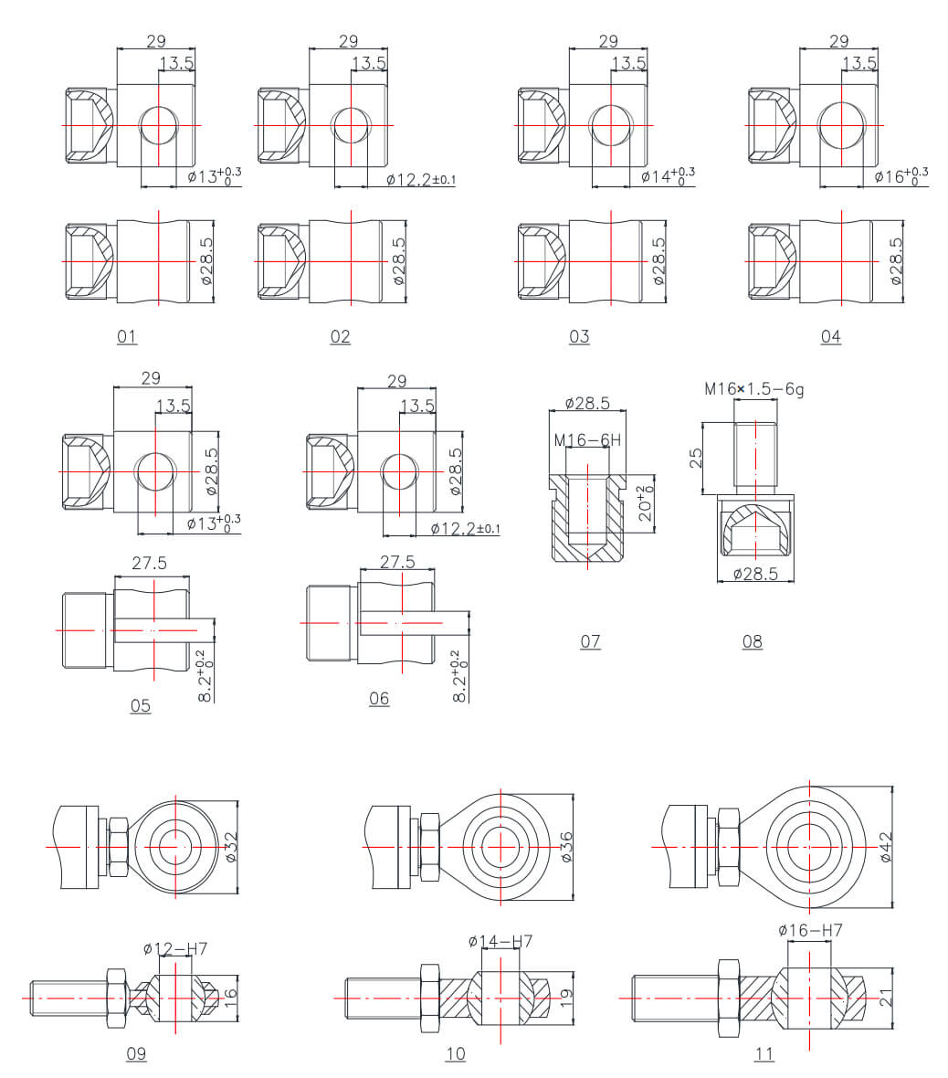
Rear
Give Us A Message
Related Products
Ask For A Quick Quote
If you are looking for more information on our services, or how we could potentially help, we would love to hear from you!