
Products
Our company is always dedicated to providing powerful products that meet customers’ requirements and customization is available for small quantity.
Products


Feature
Max.load 8000N
Product class IP65
Compact mechanical system
Built-in limit switches
Imported POT/HALL sensors (options)
CE certificated
Widely work in the harsh environment
PDF Download
Basic Spec.

Technical Info
Mounting length
Dimension
S: Stroke, the travel length of actuator
L: Length, the fully retracted length of actuator from front hole centre to rear hole centre

Hall Sensor Signal
POT
Signal Output
Standard limit switch diagram

Limit switch signal output

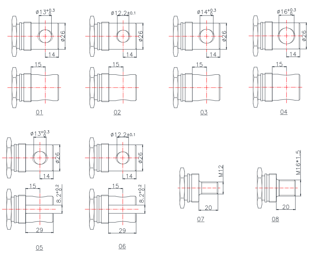
Attachment Options
Front
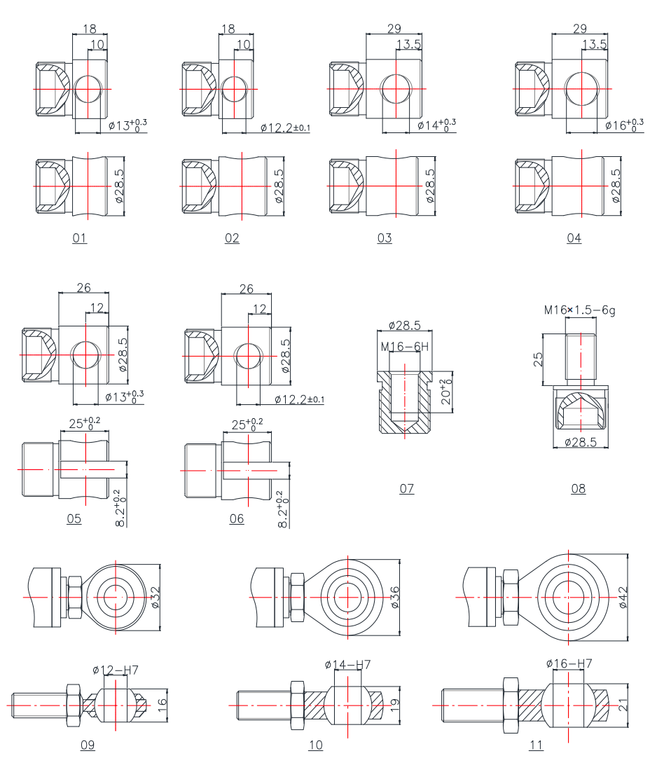
Rear
Give Us A Message
Related Products
Ask For A Quick Quote
If you are looking for more information on our services, or how we could potentially help, we would love to hear from you!